
CaveWhere uses a process called Carpeting to morph sketch projections. In this process, CaveWhere scale and rotates, grids, and warps a sketch to match a survey line plot. Loops can be closed and line plots can be updated, and the sketch will re-morph to fit to the survey. But sometimes this process goes wrong, but why?!

Above, a failed carpeting profile attempt by Derek Bristol of the Chevé Cave System. “I was hoping CaveWhere would save me a lot of time by morphing profile sketches. Perhaps not…“, Derek. Hopefully, this article will shed some light on CaveWhere’s carpeting algorithm and help you make better 3D cave maps from 2D sketches and save some time.
Scrap Scale and Rotation
To Carpet a sketch, CaveWhere must first scale and rotate the sketch. Scaling and rotating the sketch lines it up with survey data. For all projections, the values for scale and rotation are the most important values for having an accurate carpeting result. Below shows the difference between selecting good and poor scale values.
 |
 |
 |
|
Scale at 50% |
Correct Scale (100%) |
Scale at 150% |
| As shown above, having a scale that is too small will cause the passage to become thin. A scale too large will cause it to be fat. | ||
Below shows the difference between good and bad rotations. Rotation either North Up in plan sketches or Up in Projected Profile or Running Profile sketches.
|
 |
 |
|
Correct Rotation |
10 Degree Off |
45 Degrees Off |
Fortunately, CaveWhere includes an auto-calculate that attempts to find the best scale and rotation based on the survey data and the sketch. Auto-calculate assumes that the sketch is accurate and drawn to scale. If you get weird warping issues, make sure scale and rotation are correct. If you want the most accurate results, manually enter the correct scale and rotation values. CaveWhere comes with a North Up tool and Scale tool to quickly get the correct rotation and scale. See videos below. After scaling and rotating the scrap, CaveWhere moves on to gridding.
Above, the North Up tool. This calculates the North or Up of the survey notes. A good sketcher will mark what direction North is on the page.
Above, the scale tool. If the Image Resolution is set correctly, this will find the correct scale for the scan notes. In the video above, the notes were capture using a cell phone camera and the Image Resolution isn’t accurately set. By default scanner will set the image resolution correctly in the image’s metadata. Using the scale tool, correctly finds the correct scale from a scale bar drawn on the survey notes, even if the Image Resolution is wrong.
Scrap Gridding
CaveWhere creates a regular grid of squares across the sketch. The grid is clipped along the scrap boundaries. Currently, in version 0.09, the grid size is fixed but could possibly be an option to choose in the future. Once the scrap is gridded, CaveWhere then morphs each point in the grid.
 |
 |
|
The blue grid is generated by CaveWhere for each scrap. |
The grid is then clipped to the scrap boundaries. |
Morphing
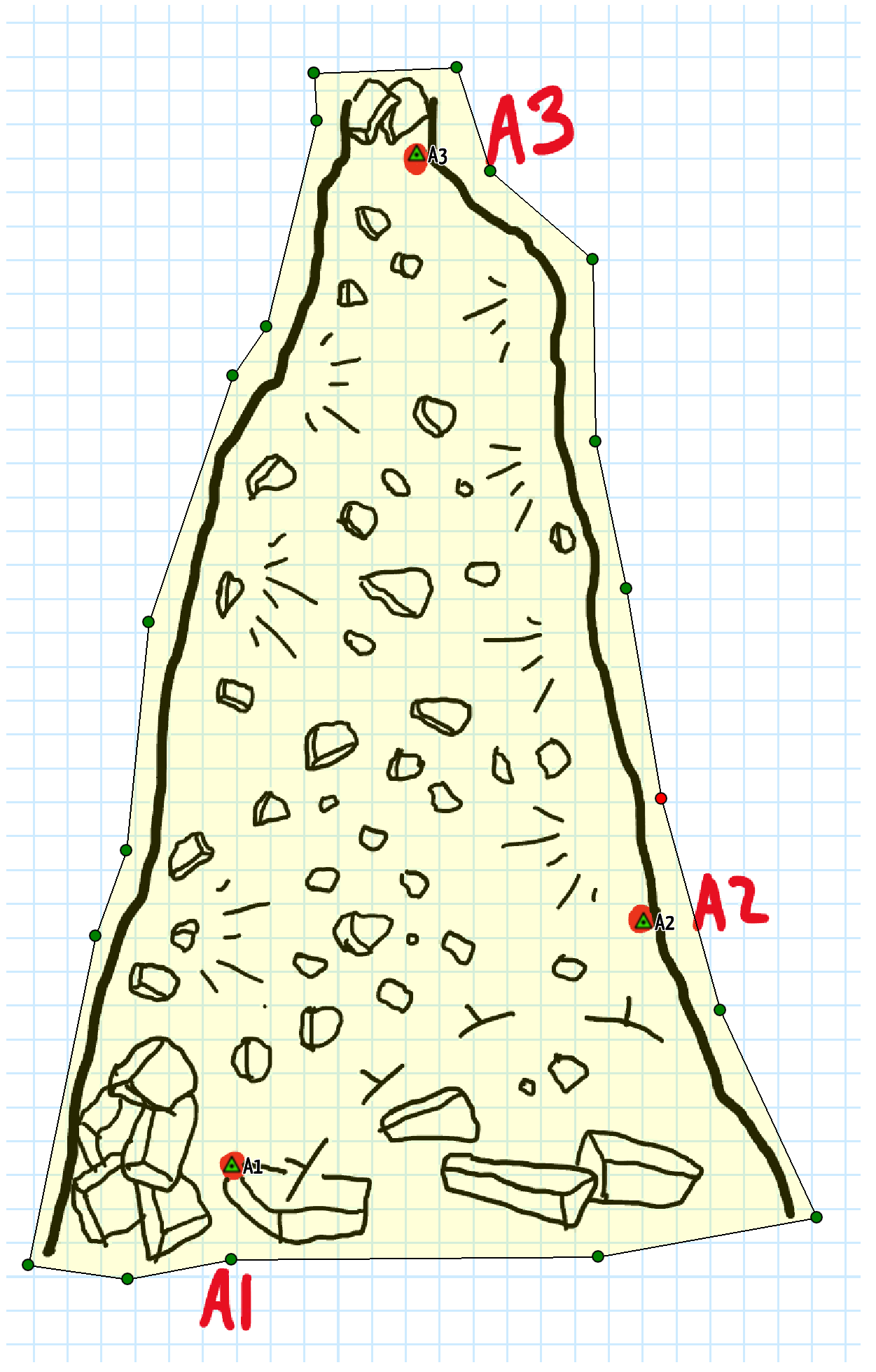
For each grid point, CaveWhere projects that point relative to each station in the scrap. This process creates a list of proposed positions (e.g. x, y, z) for that scrap grid point. CaveWhere takes that list and uses a non-linear weighing algorithm to prioritize proposed positions from nearby stations and discounts stations that are far away. With the weights, the proposed positions are summed and the final position for the grid point is generated. This is more or less an average of where the grid point should be.

For grid point P, the three proposed locations (i.e. P1, P2, p3) generate in respect to each station: A1, A2, A3. The 3 proposed locations averaged together (point R) using a non-linear weighting algorithm based on distance to the station. For example, A3 is the farthest station from P1 so it contributes the least amount to the final position of P. On the other hand, A1 is the closest and will contribute the most. If the drawing sketched to scale, P1, P2, P3 will be relatively close to P. This example is exaggerated to illustrate the algorithm.
Finally, CaveWhere places the scrap image over this grid, creating the final carpeted result. In the Plan scrap, each scrap grid is morphed with all stations in the scrap. Using all the stations makes the warping continuous and prevents unappealing discontinuous steps in the results. The main drawback to using all the stations is that unrelated stations can affect the final morphed result. This is particularly apparent in the elevation of a plan morph. In CaveWhere version 0.9, plan carpeting can have localized vertical bumps. These localized bumps are undesirable, and will hopefully be fixed in future versions of CaveWhere. See below as an example.

This shows the Plan sketch being morphed and displayed in profile. Notice how CaveWhere uses the elevation of upper station to affect the lower scrap elevation making an artificial bump.
Profile Morphing
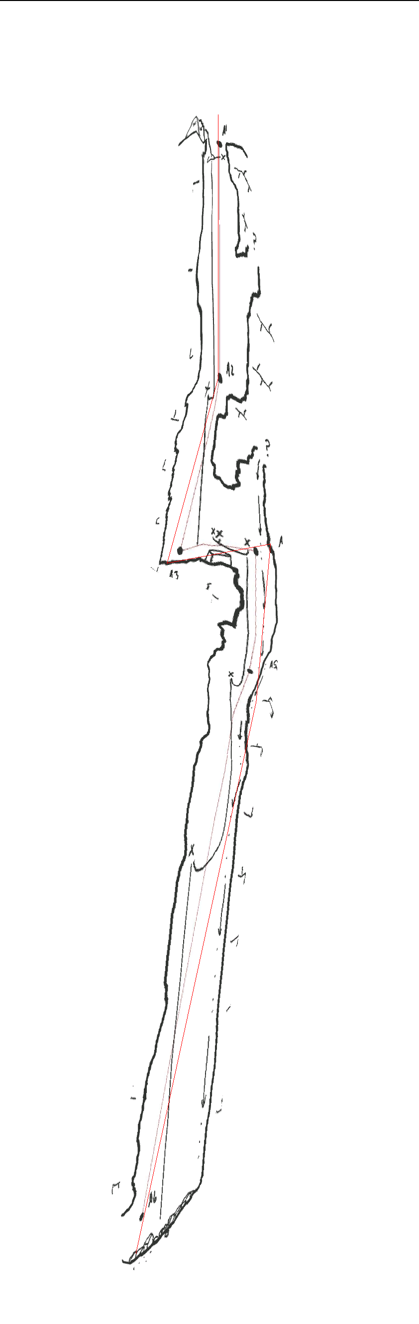
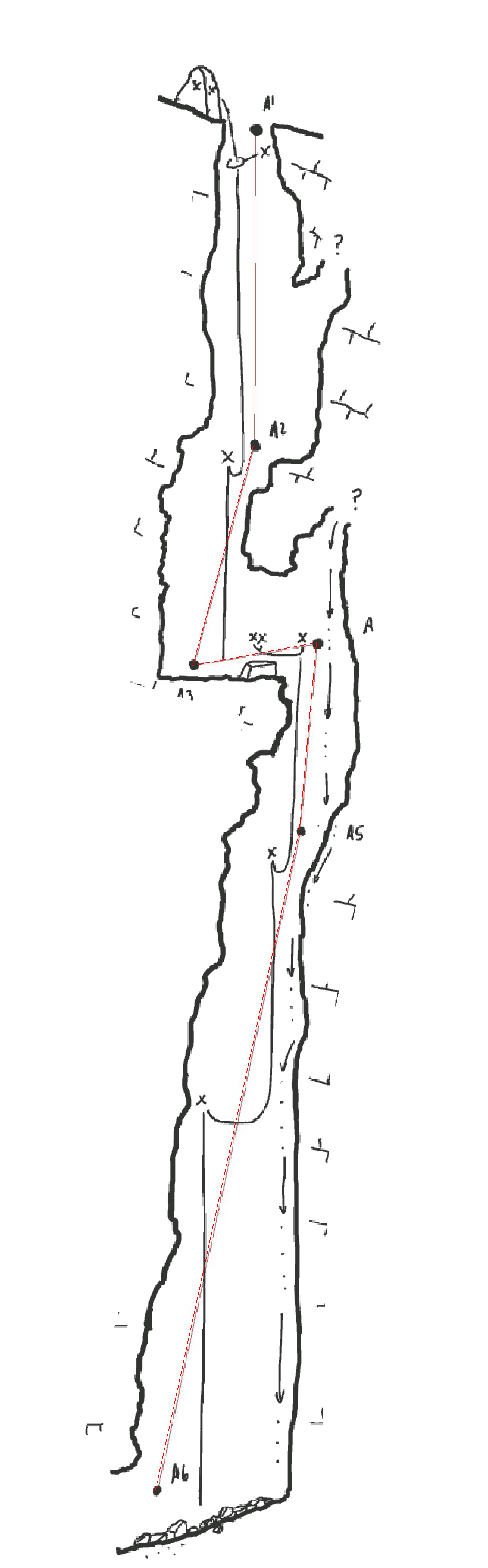
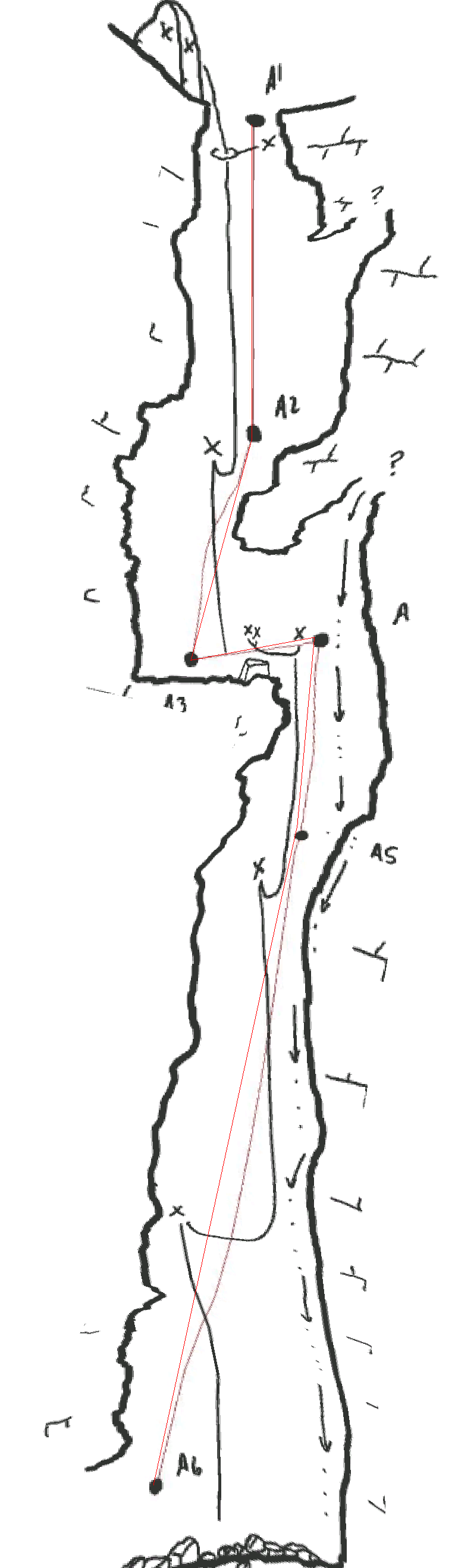
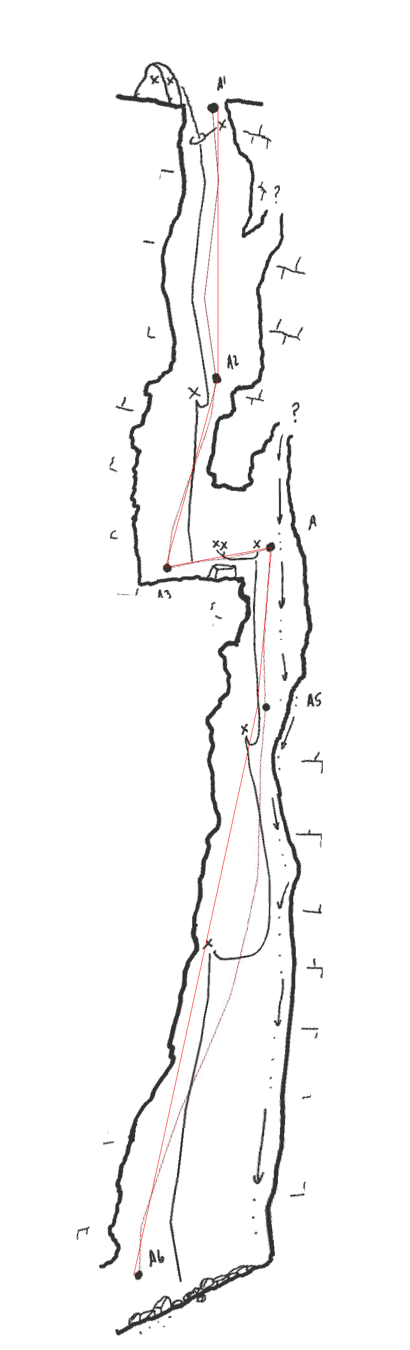
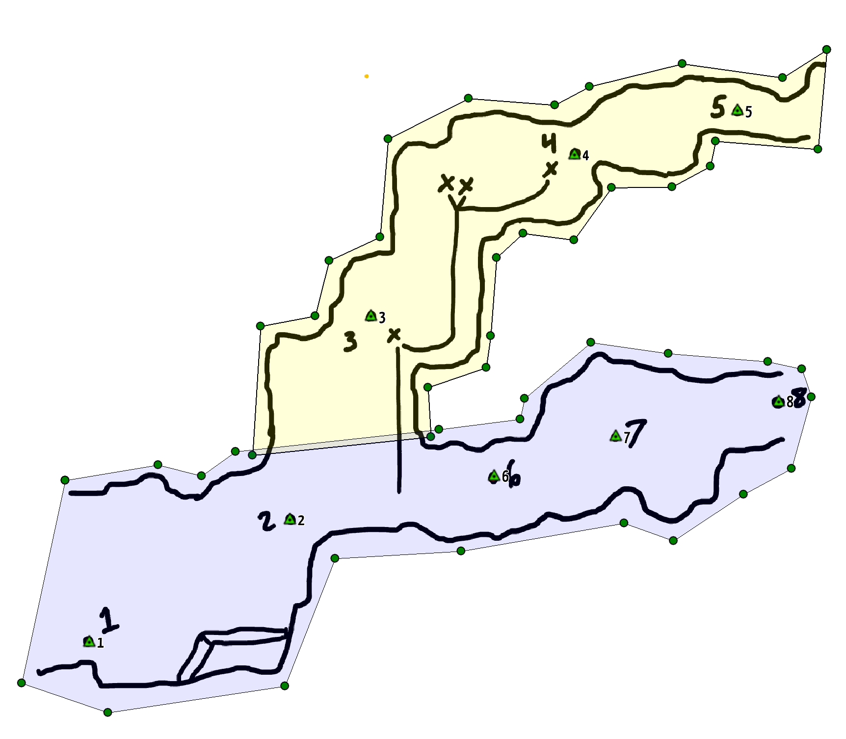
Running Profile scraps uses the same weighting algorithm as the Plan warping with some major caveats. Going back to the grid points, in Running Profile scraps, each grid point is assigned to only two stations in the scrap. This assignment happens from the left side of the scrap to the right side of the scrap. For example, below shows how this assignment happens.

From left to right, the first section (in red) from A1 to A2, then A2 to A (blue), followed by A3 to A4 (yellow) and finally A4 to A5 green.
After assignment occurs, CaveWhere creates a projection profile plane between each pair station. The projected profile plane azimuth changes between station pairs. This make the Running Profile inherently discontinuous and is the desired result, see video below.
The main downside to this approach is that Running Profile can only operate on a single continuous leg without branches. Also, the sketch should not overlap vertically. When scraps overlap vertically, CaveWhere will align a single projection plane to multiple branches. This assignment will cause undesirable morphing. See below.

Running Profile warps from left to right. If using a single scrap for the sketch above, CaveWhere will morph from 1 → 2 → 3 → 6 → 4 → 7 → 5 → 8. This station alternating will cause seesawing morphing, shown in the video below.
The solution to overlapping vertical scraps is to break the sketch into multiple scraps.
The image above shows breaking the sketch into multiple scraps, purple and yellow. Note that scraps can overlap.
The resulting running profile warping with when breaking the sketch into multiple parts.
Using Running Profile scraps for rendering large vertical shafts can also be problematic, since the horizontal distance between stations is relatively small, and shot azimuths tend to spiral down pits. Below is an example of warping artifacts generated by a vertical shaft. The solution to this is to use Projected Profile scrap, described in the section below.
Using running profile wrap with stations vertically stacked, the warping causes a unwanted crease from Station 2 down to Station 6.
Above, project profile scrap. Using Project profile removes this crease and produces a pleasing result.
Unlike Plan scraps, running profiles requires at least two stations. This prevents CaveWhere from rendering cross-sections with running profile scraps. CaveWhere will generate the running profile warping plane between any two stations in the sketch, even if the stations are connected with a survey shot. This can be especially useful for fixing warping artifacts by ignoring stations that generate warping issues.
Projected Profile support is a new feature in CaveWhere 1.0. You can preview this feature by supporting CaveWhere on Patreon (get early releases and more)! Checkout this article for details on Projected Profile Support.
Trouble Shooting Carpeting
- Make sure the line plot is being generated. If line plot doesn’t exist in the 3D view, there’s an error. CaveWhere need the line plot for carpeting
- Check that Scale and North or Up are calculated correctly and entered correctly. Use Scale and North Up tool to extract the correct values of each.
- Delete misbehaving stations
- Reducing the number of stations helps to determine errors in the survey sketch. Sometimes sketchers mislabel stations.
- Make sure station names are correct and are in the correct location
- CaveWhere uses all station names in the cave and not just the stations in the current survey trip. Mislabeled stations can cause severe warping errors.
- Break the scrap into multiple scraps for independent morphing
- Use Running Profile for horizontal passage and Projected Profiles for shafts and pits with vertical shots.
- For Projected Profiles make sure the profile azimuth is correct.
1 thought on “Sketch Carpeting Behavior and Troubleshooting”