
CaveWhere’s Patreon supporters make new features like Projected Profiles possible. Become a supporter and get early access and download this feature.
Projected Profiles
In practice, most cave sketchers will draw vertical shafts with projected profiles. Unlike running profiles, where the profile plane changes per shot, projected profiles use a fixed plane (illustrated below). Sketchers use running profiles for horizontal passage and projected profiles or vertical shafts. Projected profile prevent morphing profile issues.
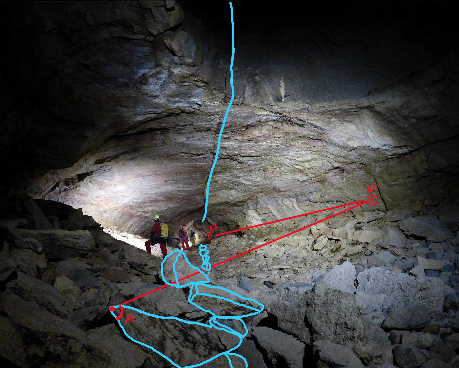
When using plan scraps, this projection plane is always parallel to the ground. Vertically oriented projected profiles need an azimuth. Without the correct profile azimuth, CaveWhere will incorrectly warp a projected profile sketch.
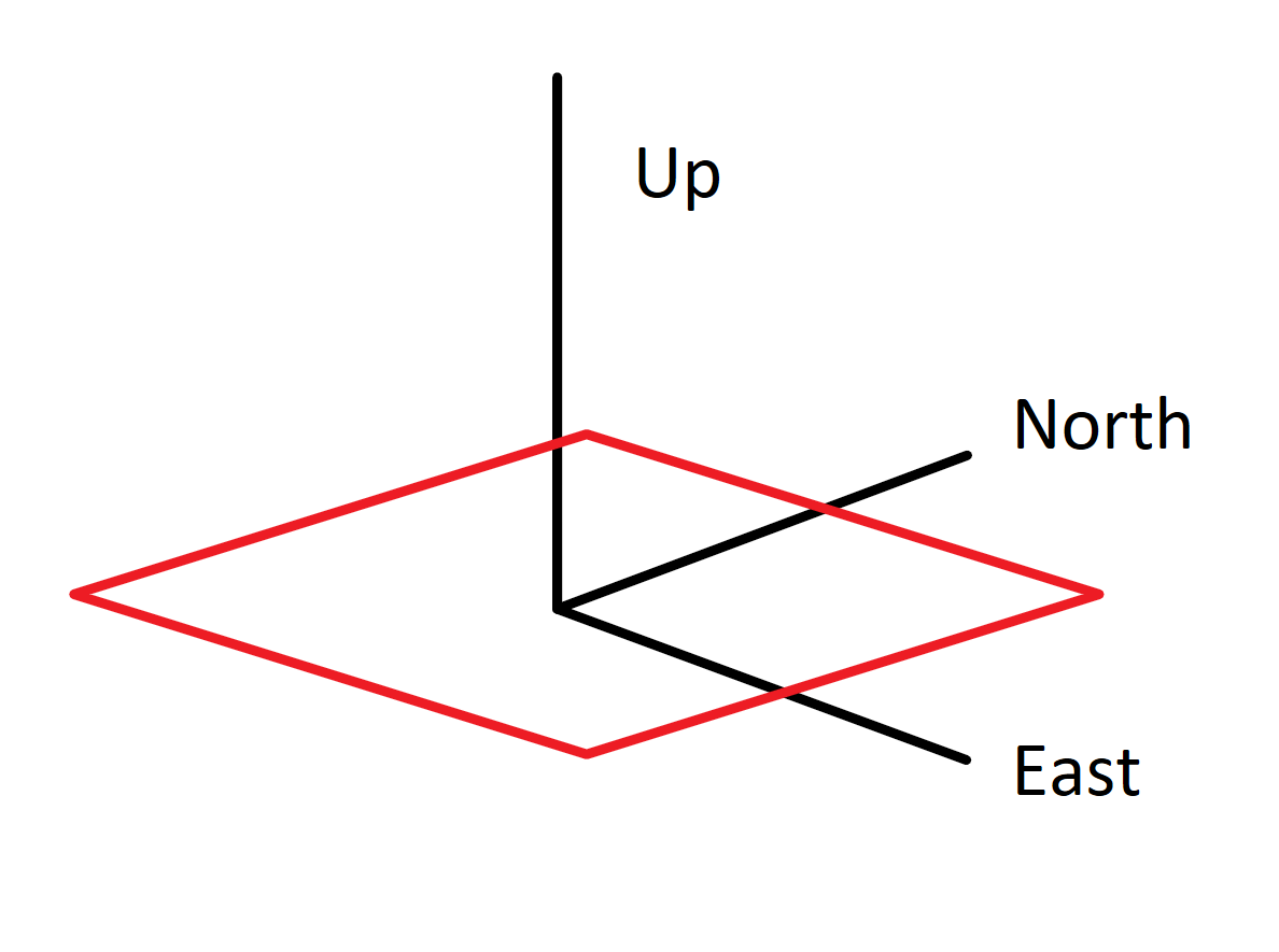
The plan scrap uses the ground as the projection plane, shown in red.
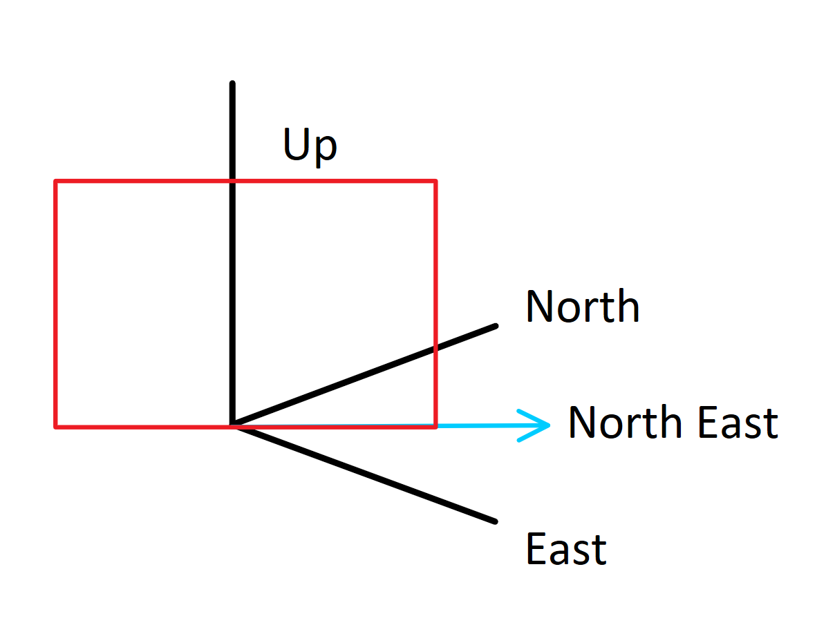
Projected Profiles use the vertical plane (red rectangle) with an azimuth, in this case 45° (north east) with the options Left to Right.
Choosing the right Azimuth
Luckily, CaveWhere can automatically calculate the profile azimuth, if Auto Calculate is selected and the scrap is drawn to scale. CaveWhere searches for the best azimuth by iterating through all orientations (0 to 360°) and finds the orientation that has the least morphing error. Automatic calculation of the azimuth only works if the scrap has more than one shot that is not purely vertical (i.e. +90 or -90 angle) and is sketched to scale. If CaveWhere gets the azimuth wrong, users can enter the projected profile azimuth manually, by disabling Auto Calculation. When using manual profile azimuth, there are three options:
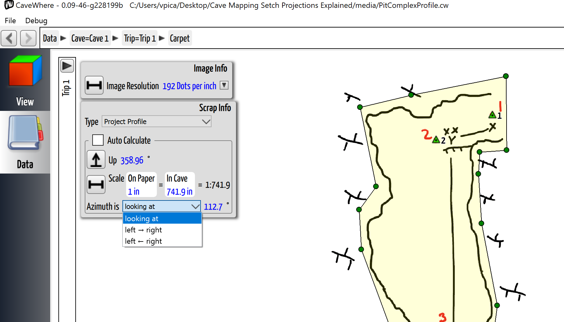
This image shows the profile azimuth options. For this scrap, the azimuth is looking at 112.7°.
- Looking At
This is the azimuth direction as if you were looking through the sketch. This is perpendicular to the sketch. If you go into View and go to a particular azimuth, this will be the azimuth you want to use for Looking At. In the example sketch below, this would be 135°.
- Left Right
This is the azimuth direction from the left side of the page to the right side of the page. In the example sketch below, this would be 225°.
- Left Right
This is the azimuth direction from the right side of the page to the left side of the page. In the example sketch below, this would be 45°.
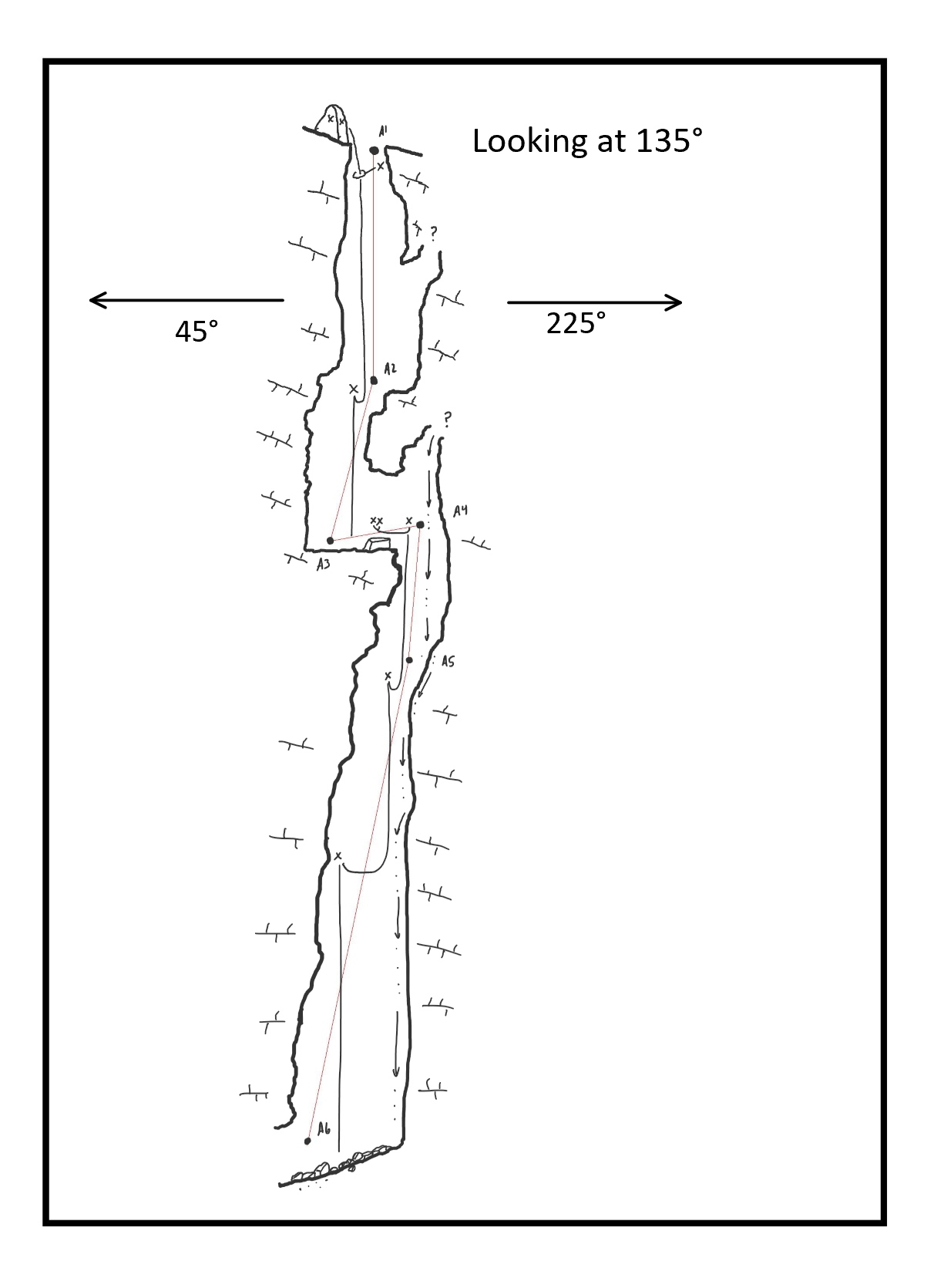
The scrap above shows values of the profile azimuth. Typically, cave sketchers will write the direction the profile is orientated.
Cross-Sections
Since cross-sections are projected profiles with 0 or 1 survey stations, CaveWhere supports them with some restrictions. First, CaveWhere only supports cross-section at station locations. Mid shot, cross-section locations are not currently supported but hopefully will be supported in the future. Second, since the cross-section only has one station, CaveWhere cannot automatically calculate Up, Scale, and projected profile azimuths. Users will have to enter them manually. Finally, the cross-sections must be drawn to scale.
1 thought on “Projected Profiles Support”