
Cave Mapping Sketch Projection
Cave Surveyors typically use four different views to draw cave passage: Plan, Running Profile, Projected Profile and Cross-Sections. CaveWhere can visualize all 4 supports slices using it’s carpeting algorithm. Future blog post will describe the carpeting algorithm in detail, plus potential issues and a troubleshooting guide.
|
Sketch Projection |
CaveWhere Version |
|
0.08 and earlier |
|
|
0.09 |
|
|
1.0 (partial support) |
Plan
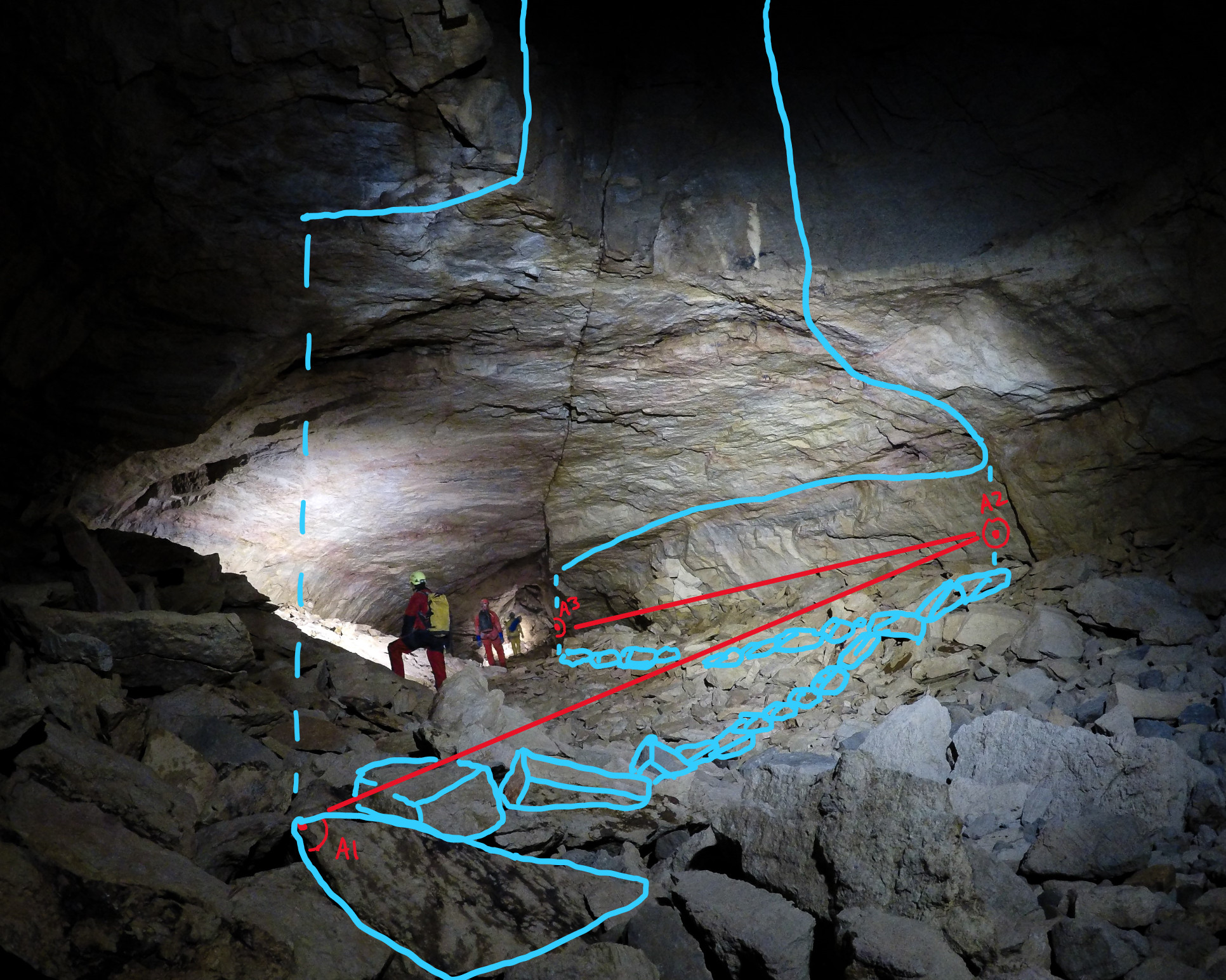
This view is an orthographic projection looking down and is the floor plan of the cave. Below, shows a cave passage photo with illustrations and symbology of plan view sketch.

Below is the resulting plan view sketch created from mapping the cave passage in the previous photo.
Profiles
Profiles come in two variants: Projected Profile and Running Profile.
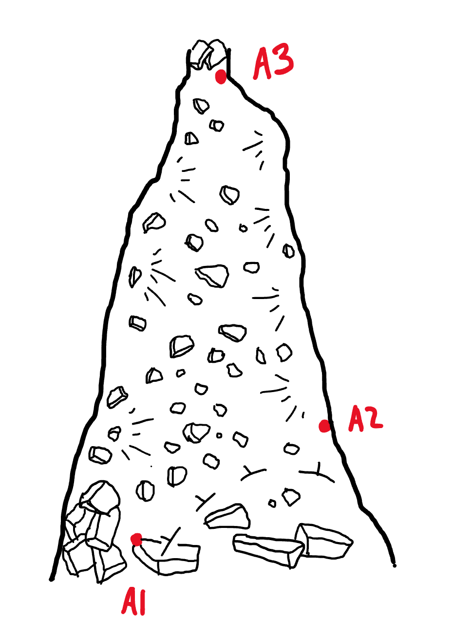
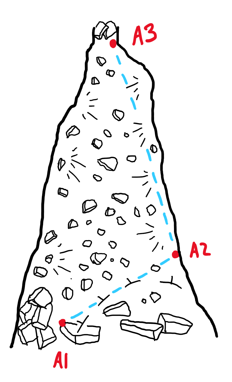
Projected Profile
Just like the Plan, a Projected Profile is a vertically-oriented orthographic projection. Cave passage is drawn along a vertical plane aligned along an azimuth (compass bearing) that best represents the passage. Cavers generally use Projected Profiles to draw large vertical shafts. Profiles represent the vertical extent of the cave.
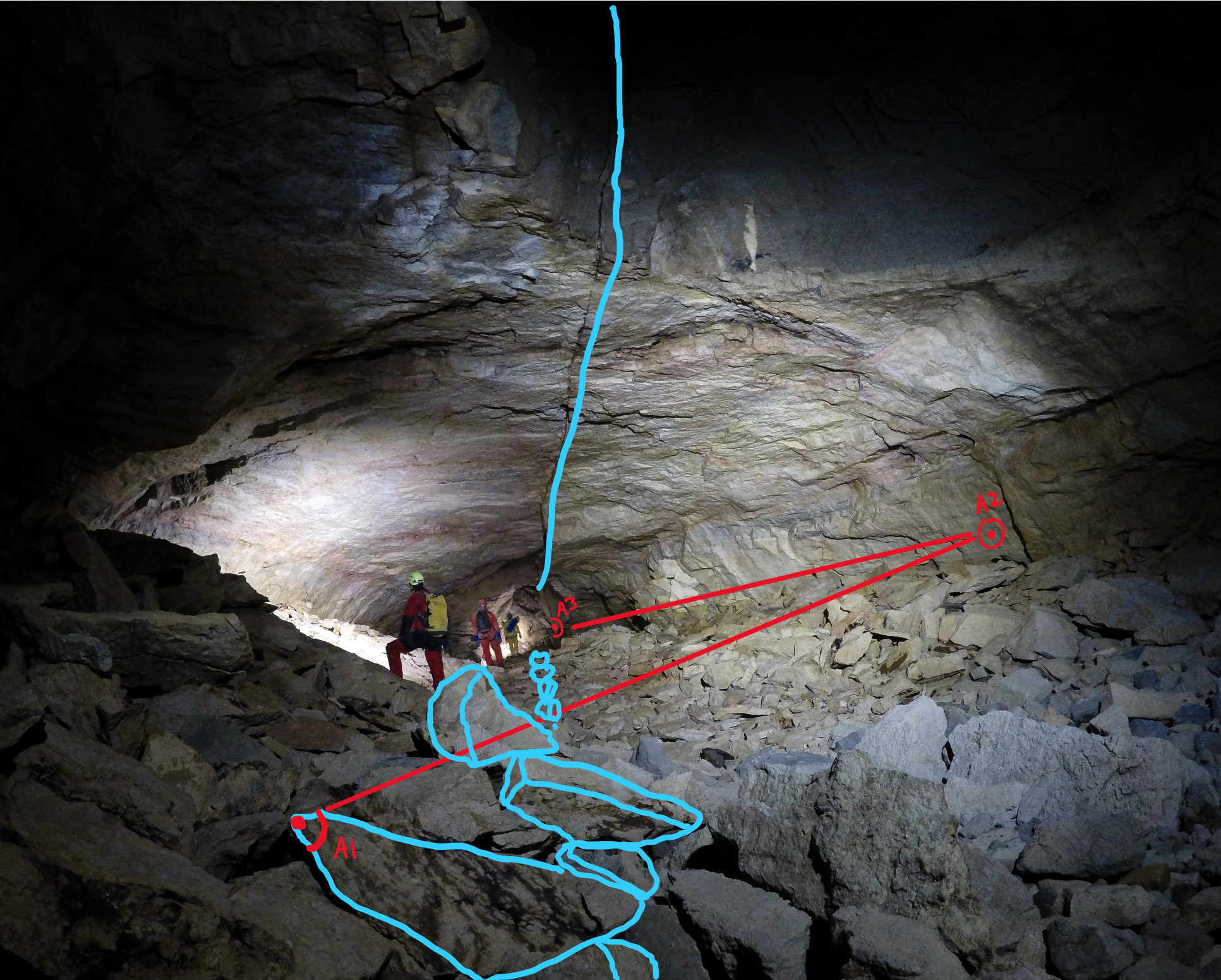
Above, a cave passage photo with illustrations and symbology of a Projected Profile sketch.
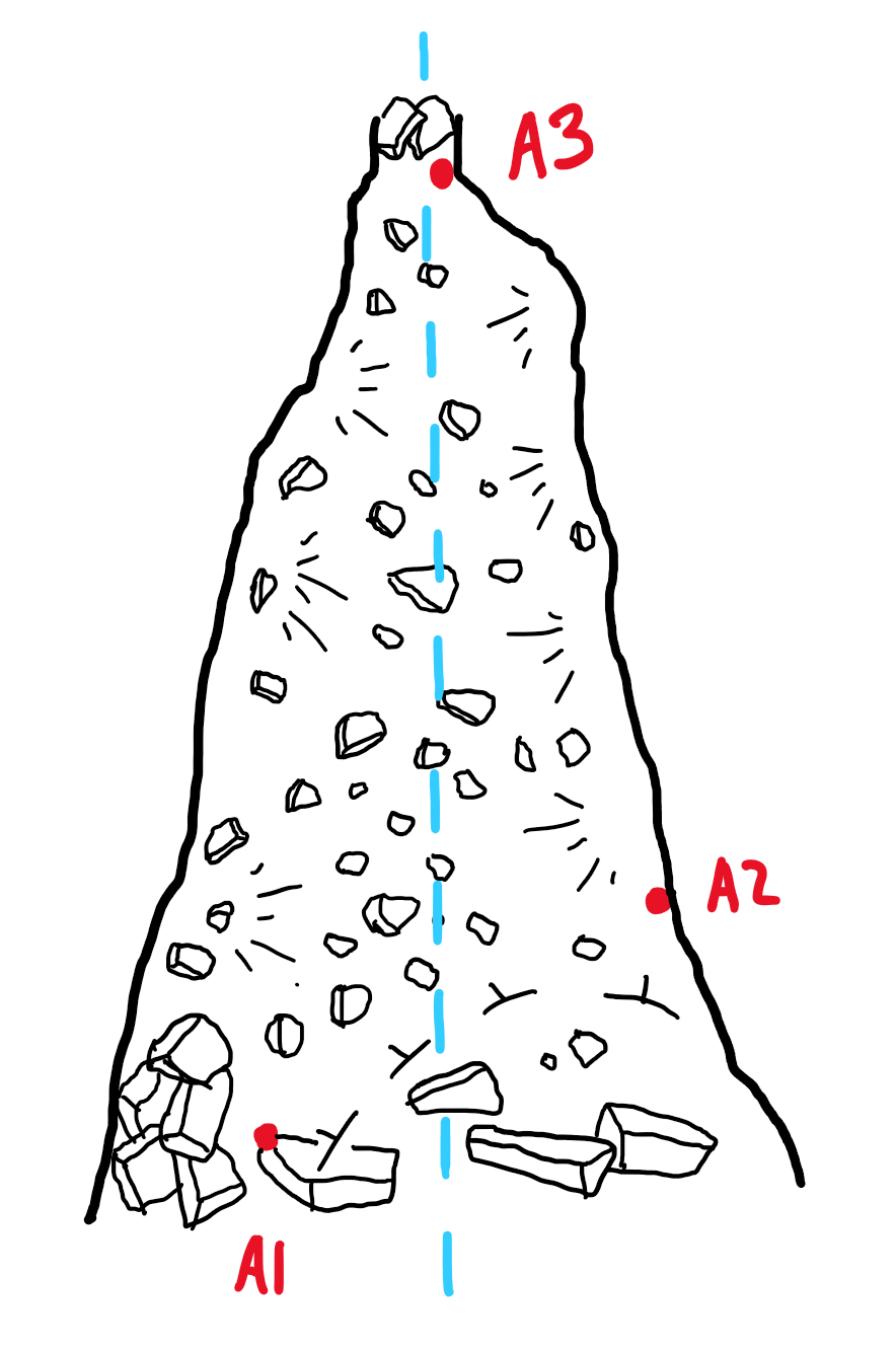
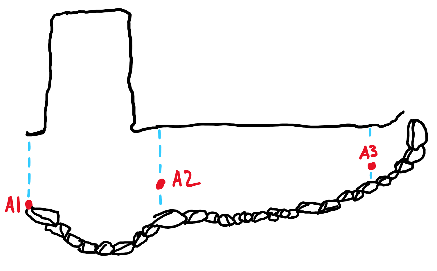
Above, the plan view sketch with dotted blue line showing the vertical slice representing the Projected Profile sketch below. Note that the shot length from A1 -> A2 is shortened.
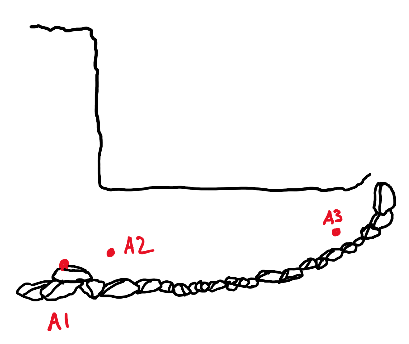
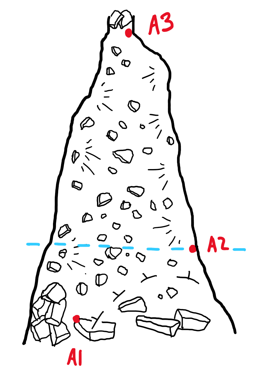
Running Profile
Just like a Projected Profile, Running Profiles represent the vertical extent of the cave. The main difference is the azimuth of the running profile changes per survey shot. This allows the Running Profile to wrap around corners as the cave passage meanders. Running profiles will maintain shot length.
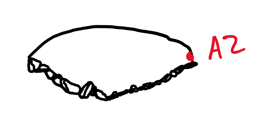
Above, a cave passage photo with illustrations and symbology of Running Profile sketch.
Above, the plan view sketch with dotted blue line showing the 2 vertical slices representing the Running profile sketch below. Note that the shot length from A1 -> A2 is maintained and isn’t shortened like the Projected profile.
Cross-Sections
Cross-Sections are specially projected profiles that are drawn as a vertical slice perpendicular to the passage direction. Generally, Cross-Sections are drawn at most survey stations or between survey shots.

Above is a cave passage photo with illustrations and symbology of a cross-section sketch.
Above, the plan view sketch with dotted blue line showing vertical slices representing a cross-section sketch on the below.
2 thoughts on “Cave Mapping Sketch Projections”